Maya offers a powerful modeling system known as NURBS—Non-Uniform Rational B-Splines. NURBS modeling is not simply putting objects together. Unlike fixed polygons , NURBS create 3D objects from curves and surfaces. Therefore, NURBS can be modeled in a variety of ways.
NURBS modeling is considered a better alternative to SUBd modeling as it gives you more precise control. They have their own rules and limitations for how you can build, attach, and cut them, but in general, they are quite flexible. The faceted, low-resolution look that often occurs when creating curved surfaces with polygons is easily handled in NURBS models, which can display curved surfaces as virtually any number of polygons.
To make it a little simpler, however, NURBS are simply a variation of splines, which are used to define a curve. Curves are the basis for the underlying mathematical structure of what makes up a NURBS surface. Nurbs modeling has capability for creating:
- organic ,flowing surfaces such as animals, human bodies and fruits.
- Industrial surfaces such as automobiles, clocks and toasters.
- Smooth surfaces adjustable over broad areas with few control points.
Nurbs Primitives
Nurbs primitives are common geometric objects such as spheres, cubes and cylinders. They are often used as the foundation for other shapes.
Sphere
Select Create > Nurbs primitives >Sphere. After you set the options ,click the Create button.
Pivot
By default, the pivot is set to Object and the primitive is created at the origin. If you set Pivot to User defined, you can enter values in the Pivot point X, Y and Z boxes to position the pivots.
Axis
Select X, Y or Z to specify a preset axis direction of the object. Select Active View to create the object perpendicular to the current orthographic view. The Active view option has no effect when the current modeling view is a camera or perspective view.
Sweep Angles
These options let you create a partial sphere by specifying a degree of rotation. Degree values can range from 0 to 360 degree.
Radius
Sets the width and depth of the primitive.
Surface Degree
A linear surface has a faceted appearance : a cubic surface is rounded.
Sections
Set the number of surface curves created on the sphere in one direction. These curves are also called isoparms, show the outline of the surface shape.
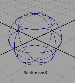
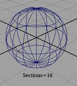
Fig 3-1 Sections
Spans
Set the number of surface curves created on the sphere in the direction that crosses the section direction.
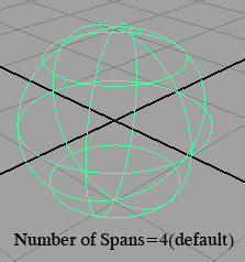
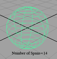
Fig 3-2 Spans
Cube
A cube has six sides, each of them is selectable. You can select a side of the cube in the view or click its heading in the outliner.
Width, Length and Height sets the cube dimensions.
Cylinder
You can create a cylinder with or without end caps. End caps is a unique feature to the creation of the cylinder. You can create caps for either, both or no ends of the cylinder.
Cone
You can create a cone with or without a cap on its base.
Plane
A plane is flat surface made up of specified number of patches .
Torus
A torus is a 3d ring.
Circle
A circle is a curve not a surface. Its features are similar to the sphere.
Curves
The foundation of a Nurbs surface is a curve. Surfaces are web of interconnected curves. The curves help you create and modify surfaces. Proficiency at drawing and editing curves is an important part of Nurbs modeling.
You can not render curves. With Nurbs curves ,you can position points on a curve or surface exactly where you want them and reshape the curve or surface by moving just a few control points that lie on or near the curve. Examples of NURBS primitives are spheres, cubes, cylinders, cones and planes.
A major advantage of modeling with NURBS in Maya is that you can convert any NURBS object to Subdivision Surfaces (also called "SubDs") or polygons at any time.
Using NURBS can have its drawbacks, however. When modeling a character that needs to be animated, you might notice seams, or even visible gaps, between NURBS surfaces .As a result of the way NURBS are constructed, you rarely come up with an object composed of a single surface, and the surfaces must meet together exactly to avoid these problems.
Elements of a Curve
The elements of a curve follow:
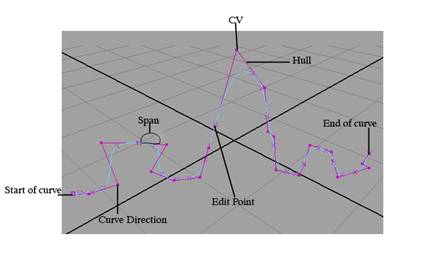
A curve point is an arbitrary point on the curve. It can have the same position as a CV or edit point.
CVs are control vertices ,These points often lie away from the curve.
Edit points are also called knots. You can move these points to reposition a specific point on the curve. You can't move the edit points of a surface.
The start of a curve is the first point of the curve created when you draw the curve.The end of the curve is the last point of the curve you create. You need to know which points are the start and end points for certain modeling operations.
The curve direction is displayed as a small letter u.
A hull is a network of straight lines that connects CVs. Hulls are mainly visual aids to see where interconnected CVs exist.
A span is the point of a curve between the two edit points. If you add extra edit points to a curve enhance your control of its shape, you increase the number of spans. you don't select and manipulate a curve span directly.
Fig 3-3 Elements of curve
Tools for Creating Curves
There are three tools for creating curves
- Create > CV Curve Tool
- Create > EP Curve Tool
- Create > Pencil Curve Tool
CV Curve Tool
This Tool creates the curve's CV exactly where you click them. It creates edit points based on where you create the CVs. When it turns white, you have created enough CVs to complete the curve. You must create at least four CVs when you use the default option settings.
EP Curve Tool
The EP Curve Tool creates the curve's edit points exactly where you click them. It creates CVs in positions based on where you create the edit points. EP stands for edit points. You must place at least two edit points to create the curve.
Pencil Curve Tool
The Pencil Tool lets you draw a curve by dragging the mouse or by using a digitizing pen and tablet. When you create a curve using the Pencil Curve Tool, you can not delete curve segments by pressing the Backspace key.
Maya creates a trail of edit points and sometimes several curves where you drag the mouse or pen. The CVs created with this tool might seem to pose efficiency and control problems, you can simplify the curves with Edit Curves > Rebuild Curve.
Attaching curves
Use Edit Curves > Attach Curves to create a single curve from two curves.
Attach Method
Connect joins the curves with minimal curvature smoothing at the joint point.
Blends smooths the curvature at the joint point based on the blend Bias value.
Detaching Curves
Use Edit Curves > Detach Curves to break a curve into two curves or to open a closed curve.
Construction Plane
Use Create > Construction Plane to create a plane as a construction aid. You can not rotate a construction plane, make it a live surface, then draw a curve on it. You can not render or animate a construction plane.
Select create > Construction Plane to open the option window.
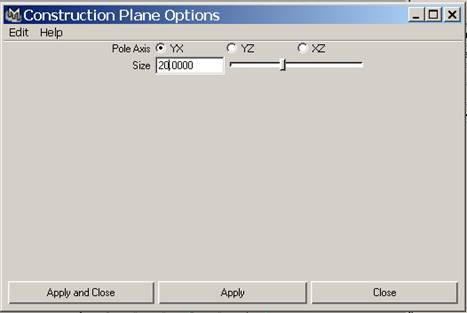
Fig 3-4 Construction plane options
Pole Axis
Sets the orientation of the construction plane. The default is an XY plane.
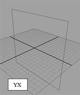
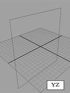
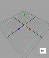
Fig 3-5 Orientation of the construction plane
Size
Sets the size of the plane in grid units.
Extending curves
Use Edit Curves> Extend >Extend curve to extend a curve beyond its original creation length. To extend a revolve surface ,you can extend the curve used by the revolve operation.
Select Edit curves > Extend > Extend Curve and set the desired options.
Click the Extend button.
By default the curve is extended 2 unit at its end.
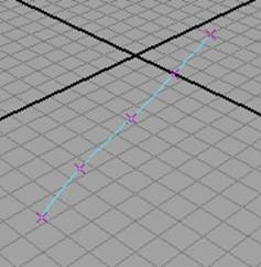
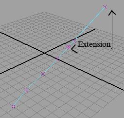
Fig 3-6 Extending curves
Reversing the curve direction
Select Edit Curves > Reverse Curve Direction.
Rebuilding curves
Use Edit Curves > Rebuild curve to rebuild a Nurbs curve or curve on surface to smooth it or lessen its complexity.
Lofting Curves and Surfaces
Lofting is used to construct a surface that passes through a series of profile curves. The curves can be curves -on -surface, surface isoparms or trimmed edges.
With the help of Loft feature, you can create intermediate areas between any two surfaces created with boundary curves. Before you begin ,you need at least two profiles curves or surface isoparms.
Pick the first curve you want to loft, then shift-click to pick subsequent curves.
Select Surfaces >Loft
You can add new curves to an existing lofted surfaces created with construction history.
Birail Tools
Birail Tools that create a surface by sweeping one or more profile curve along two rail curves. Birail 1 sweeps one profile curve, Birail 2 sweeps two, Birail 3+ sweeps three or more.
Before using Birail Tool ,you must check all workspace to make sure the profile curve (s) intersected the rail curves. Profile and rail curves can be isoparms, curves -on-surface,trim boundaries or boundary curves of an existing surfaces.
Select Surfaces > Birail >Birail n Tool.
Beveling Surfaces
Bevel is used to create an extruded surface with a beveled edge from any curve, including text curves and trim edges. You can bevel surfaces for instance, to create a ledge on a building or the rolled edge on an upholstered chair.
Click the curve you want to bevel and select Surfaces > Bevel.
Bevel width
This value specifies the initial width of the bevel as viewed from the front of the curve or isoparm.
Bevel Depth
This value sets the initial depth of the bevel part of the surface. The combination of bevel width and depth sets the bevel angle.
Extrude Height
This value specifies the height of extruded portion of the surface, not including the bevel surface area.
Bevel Corners
This options specify how corners in the original construction curves are handled in the beveled surface.

Custom Search


0 comments:
Post a Comment