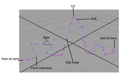
Maya is the 3-D animation software that provides a number of tools for creating complex characters and animations. Maya's powerful feature set gives you an almost unlimited power to create any kind of animation. The functionality of the Maya software can be extended with the use of MEL (Maya embedded language). MEL can be used to customize the user interface and write scripts and macros. In Maya, you can create objects, lights, cameras and textures. Any object, light, camera, or just any entity can be animated by changing the value of its parameters in time. We can use Maya, to create effects or animations or movies, commercials, architectural animation and forensic animation. Maya can be used to achieve far more complex effects and animation is as compared to other software is on the shelf. This tutorial is aimed at teaching a newbie, the basic concepts and functionality of the Maya software.
Monday, November 30, 2009
MAYA Tutorial - Introduction
Posted by Lucky at 10:35 AM 0 comments
Labels: MAYA Introduction
MAYA Tutorial - MAYA Interface
- Main Menu Bar
- Status Line
- Shelf
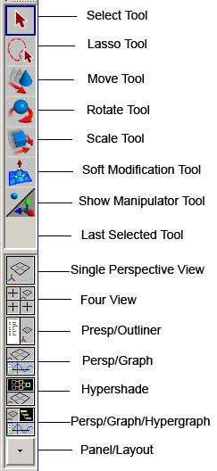
- Tool Box
- Workspace
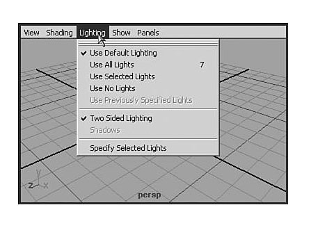
- Panel Menus
- Time Slider
- Range Slider
- Command Line
- Help Line
- Channel box
- Layer editor
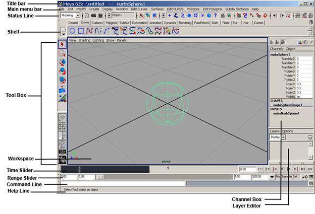 Fig 1-1 Maya User Interface
The Menu Bar

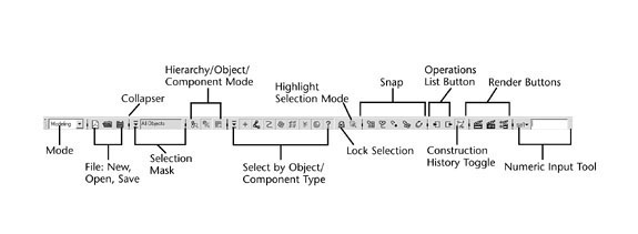


Help Line
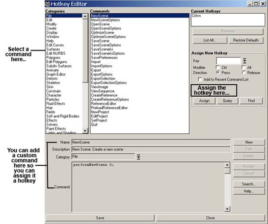
- Selecting Window>Settings/Preferences>Hotkeys.
- Select the category and command,
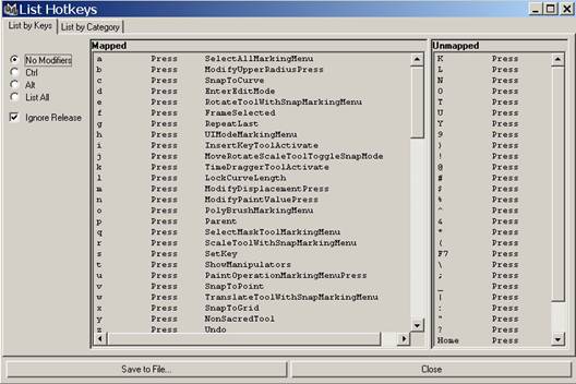
- In the assign new Hotkey area, specify the key combination .You can see a list of which keys are unmapped by clicking List All.
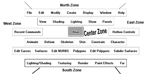
The Hotbox
Posted by Lucky at 10:34 AM 1 comments
Labels: MAYA Interface
MAYA Tutorial - Transforms in MAYA
- You can select object individually.
- You can select all objects in the scene.
- You can select objects of a specified type.
- You can select objects of a specified name.
- You can select all objects in a set.
- You can select all objects in a display layer.
Inverting a Selection
Using Transforms
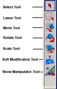
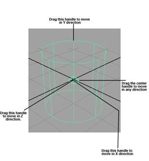
The Move Tool
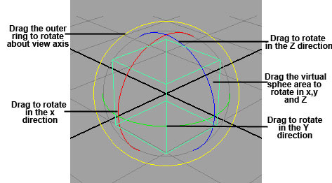
The Rotate Tool
The Scale Tool
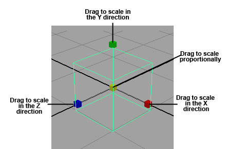
Show Manipulator Tool
Undoing and Redoing
Duplicating Objects
- Instances share the same shader as the original geometry and can not be assigned as independent shaders.
- Instanced lights have no effect.
- When you create an instance of an already instanced node, Maya does not create a new level.
- Functions like extrude and insert can not be used on instanced items.
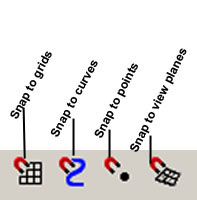
Snap to grids
Snap to curves
Snap to points
Snap to view planes
How to use the grid Snap HotKey?
To open the Outliner in the window
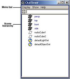
Grouping
Posted by Lucky at 10:32 AM 3 comments
Labels: Transforms in MAYA
MAYA Tutorial - Nurbs Curves and Surfaces
- organic ,flowing surfaces such as animals, human bodies and fruits.
- Industrial surfaces such as automobiles, clocks and toasters.
- Smooth surfaces adjustable over broad areas with few control points.
Sphere
Pivot
Axis
Sweep Angles
Radius
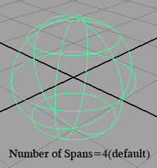
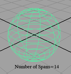
Surface Degree
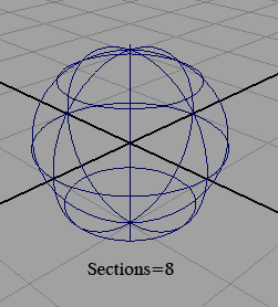
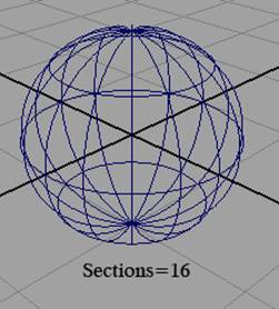
Sections
Cube
- Create > CV Curve Tool
- Create > EP Curve Tool
- Create > Pencil Curve Tool
EP Curve Tool
Pencil Curve Tool
Attach Method
Detaching Curves
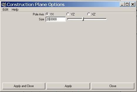
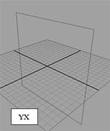
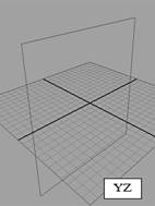
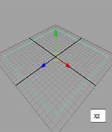
Size
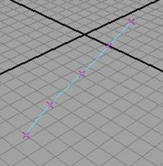
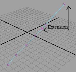
Rebuilding curves
Bevel width
Bevel Depth
Extrude Height
Bevel Corners

Custom Search
Posted by Lucky at 10:18 AM 0 comments
Labels: Nurbs Curves and Surfaces
MAYA Tutorial - Polygonal Modeling
Polygonal modeling is typically used for hard-edged surfaces that don't bend or in situations where low polygon counts are important, such as modeling for games. With Maya 5, you can easily convert between polygons, SubDs, and NURBS patches. This allows you to begin the model in one format and then convert to another, if necessary, or to use the advantages of editing or rendering a model in another format.
Polygonal Primitives
There are several ways to use primitives to build objects quickly and easily. Use primitives as a starting point, then uses a combination of polygon creation and editing operations to complete a task. The most basic object type is primitive. Primitives are pure shapes that can be used as the basis of creating more complex models. There are six polygonal primitives objects---sphere, Cone, Cylinder, Cube, Plane and Torus.
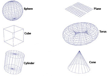
Fig4-1 Polygon primitives
To create a primitive with the default option settings, select create > Polygon Primitives and choose the primitive you want to create from the menu. You can always edit the primitive from the channel Box or its Attribute Editor.
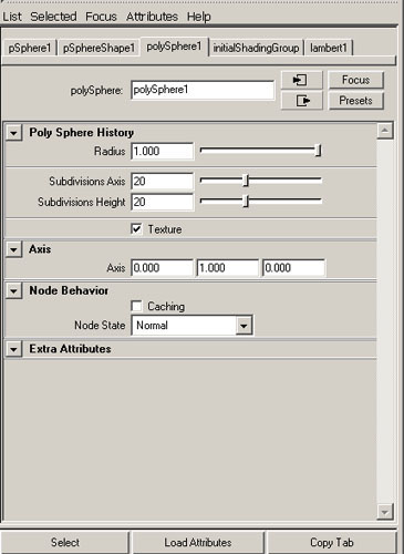
Fig 4_2 Attribute Editor
Section Radius option
The section Radius option value specifies the size of the sections .Change this value to increase or decrease the radius of sections to see the result.
Subdivision Axis
For spheres, cylinders, cones and toruses , this option defines the number of subdivisions there are around the axis defined by the Axis option. This option is also called Subdivisions Axis .Increase or decrease this value to add or take away faces around the axis defined by the Axis option.
Subdivision Height
This option defines the number of subdivisions there are along the axis defined by the Axis option. Height is equivalent to the Y directions by default.Increase or decrease this value to add or take away faces in the Axis direction.
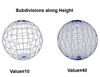
Fig4-3 Subdivision height
Creating and Editing Text
The Poly text type creates text as Polygons .When this text type is selected, a planar trim curve is created between the curves and tessellate nodes. By default, Maya creates text as Nurbs geometry.
To create polygonal text
- Select Create > Text to open the Text Curves option window and set the Type option to poly.
- Type the text you want to write in the text box.
- Change the default font settings if required.
- Change the option settings.
- Click the create button to create the text.
Polygonal Text Settings
When you create polygonal text, Maya provides option that you can set to display and create your text for subsequent polygonal-type editing.
Triangles
Three sided polygons are created. This is the default.
Tessellation Methods
Standard fit
This is the default tessellation method. It is adaptive tessellation, meaning that following option is used to determine when to stop the tessellation. The tessellation stops at the fractional tolerance value you set. If there is an edge shorter than the Minimal Edge Length, the tessellation stops on that edge. If the surface is flat enough with in the edge, the tessellation stops here.
General
Set the tessellation method to General to display the following options. Unless Use chord height or use chord height ratio is turned on, a uniform tessellation is performed. Each span is split into a number of polygons depending on the number U and V values you set.
Count
Set the tessellation method to Count to display the Following slider. Count slider is used to determine how many polygons the surface can be tessellated into.
Control points
This tessellation method converts the Nurbs model to polygons while matching the CVs of the original Nurbs surface. There are no other options for this operation.
Extruding
You can pull faces and edges out from polygonal objects using the Extrude Face and Extrude Edge commands.
Extruding Faces
You can extrude faces either interactively or directly through the option window. Select Edit Polygons > Extrude Face ,set whatever option you need and click the Extrude Face button.
- If you want to extrude all the faces of an object, marquee-select the whole object to highlight the faces.
- If you want to extrude certain areas of an object, shift-or Ctrl-click to select those face only.
- If you want to extrude ,duplicate or extract multiple faces together, turn on polygons > Tool options >Keep Faces Together.
you are not happy with results, select Undo from the Edit menu, change the Extrusions settings in the channel Box or Attribute Editor and press Enter.
Extruding Edges
You can extrude edges either interactively or directly through the option window. If you prefer to set the options first and then extrude the edges, Select Edit Polygons > Extrude Face.
Duplicating Faces
You can duplicate and transform faces interactively or directly through the option window. Select the faces of the object you want to duplicate. Press the right mouse button and select Face or press F11.
- If you want to duplicate all the faces of an object, marquee-select the whole object to highlight the faces.
- If you want to duplicate certain areas of an object, click to select those face only.
You can also Duplicate Faces through Edit Polygons > Duplicate Face.
Extracting Faces
While Extracting ,Maya disconnects the selected Faces from the original shape, by duplicating the appropriate edges and vertices. The extracted faces become their own shell with in the object. This is the another way to make holes in the object while retaining their original faces.
Seperating the extracted faces creates distinct polygons out of the faces and the original object.
To extract Faces
- Select the face of the object you want to extract. Press the right mouse button and select Face from the marking menu or press F11,then shift or Ctrl-Click to select the faces.
- Select edit Polygons > Extract. The selected Faces are extracted.
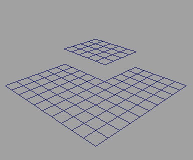
Fig4-4 Extracting faces
Smoothing Polygons
There are three ways to smooth polygons.
- Using Polygons > smooth.
- Using Polygons >Average vertices.
- Using the smooth operation of the sculpt polygons Tool to average the values of painted vertices to produce a smoother surface.
Polygon Selection
With Edit Polygons > Selection menu, you can constrain the selection of components to a specified area of a polygonal model and perform operations on those components in that specified area only without disturbing the rest of the model.
Select Edit Polygon > Selection >Grow Selection Region to increase the number of components you initially selected.
Selecting Boundaries
You use Edit Polygons >Selection >Select Selection Boundary to define the boundary of the current selection region. It is a quick way to select the boundaries of whatever is currently selected.
Selection a band of edges
Use Edit Polygons > Selection > Select Contiguous Edges to select a contiguous band of edges around model. With this you can select one edge, choose select Contiguous Edges, and it will select the rest of the edges in the center automatically.
Max 2d Angle ,Max 3d Angle
These settings determine how far the selection continues based on the angles between edges. The 2d angle refers to angle made by the surface topology, regardless of the surface's shape. The 3d angle refers to angles made by the surface's shape, as measured in world or local space.
Custom Search
Posted by Lucky at 10:17 AM 0 comments
Labels: Polygonal Modeling
MAYA Tutorial - Texturing and Shading
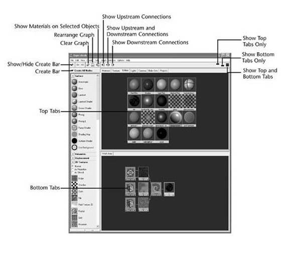
Create Bar
Tab Panels
Top Tab
Bottom Tab
This area is usually used as the Work Area—the assembly point for new materials.Basic Material Types
Lambert
Phong
PhongE
Blinn
Anisotropic
Ramp Shader
The Ramp Shader material consists of built-in ramp graphs to offer more advanced control and simplify the shader network.Ocean Shader
Layered Shader
The Layered Shader lets you combine several materials to create a more complex material.Shading Map
Surface Shader
Use Background
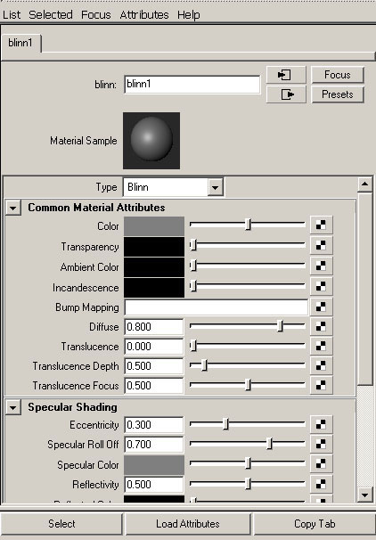
Transparency
Ambient Color
Uses Black by default. As the ambient color becomes lighter, it affect's the material's color by lightening it and blending the two colors.Incandescence
The color and the brightness of light that a material appears to be emitting. The default color value is 0.Bump Mapping
Diffuse
Translucence
Gives the material the ability to transmit and diffuse light. Light falling on a translucent surface is first absorbed beneath the surface and then diffused in all directions. The slider range is 0 to 1.Specular color
The color of shiny highlights on the surface. A black specular color produces no surface highlights. The default color value is 0.5.Reflectivity
Gives the surface the ability to reflect its surroundings or the reflected color. The default color value is 0.5.Reflected color
Represents the color of light reflected from the material. This can be used to tint a reflection.Surface Material
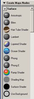
Anisotropic
Roughness
Fresnel Index
Anisotropic Reflectivity
Compositing Flag
Composites the layers using a layered shader or layered texture mode.Hardware color
Helps you distinguish the objects assigned to a layered shader in the views.Cosine power
This feature is available to the phong material. Controls the size of shiny highlights on the surface. The default value is 20.Roughness
Controls the specularity focus.Highlight Size
Controls the amount of specular highlight.Whiteness
Controls the specular highlight color. The default value is white. You can also map a texture to this value.Shading Map Color
Defines the color of the material. The default is gray.Shader
You can map any material to the shading Map material.Out color
The color of the material .The default is black.Out Transparency
The transparency of the material. The default is black.Out Glow Color
The glow color of the material. The default is black, without glow.Attributes
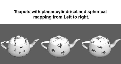
Adjust the Use Background material's to the light ,shadows, reflections and the geometry placement in the scene.Mapping Coordinates
2D Procedurals
3D Procedurals
- In the view,select the surface to which you want to assign the material.
- From Hypershade, MMB-drag the material swatch over the selected surfaces.
- In the view ,shift-select the object to which you want to assign the material and in hypershade,click the material swatch.
- While the cursor is over the material swatch in hypershade,RMB -click-drag to select assign material to selection from the pop-up menu.
- MMB-drag and drop a Hypershade swatch onto an object in the IPR Render view.
To apply a material to several surfaces from with Hypershade
- Select the surfaces in a view.
- In Hypershade,RMB-click over the material swatch and select Assign material to selection from the pop-up menu.
To apply a material to a group of faces on a polygonal surface
- Select the surface.
- Press the RMB while over the surface,select face from the marking menu,then choose the select by component type icon.
- Select the face you want to map.
- While the faces are highlighted in the view, in hypershade,LMB-shift-click over the material swatch you want and press theRMB and select Assign material to selection from the pop-up menu.

Custom Search
Posted by Lucky at 10:15 AM 0 comments
Labels: Texturing and Shading


