Monday, November 30, 2009

MAYA Tutorial - Cameras and Lighting

When Maya starts, you have four cameras by default: front, side, top and perspective. Three of them are orthographic—flat, non-perspective views—and have visible icons you can use to translate or rotate the camera. The icon for the perspective camera is, by default, invisible. These four cameras are utility views that assist you in modeling and laying out your scene. When you're ready to pick the final rendered viewpoint of your scene, you should create a scene camera. If you're shooting a series of stills, you can create many cameras, one for each shot.
The camera placement determines exactly what will be seen and is used to frame specific portions of the scene, in the same way illustrators or photographers use composition to frame certain elements in their paintings and drawings. Other key variables for cameras are focal length, rotation (orientation), and angle of view. Focal length is directly linked to angle of view; if one goes up, the other goes down. With angle of view, as the angle of the lens widens, you must move the camera closer to the subject to keep it at the same relative size in the frame. The wider the angle, the higher the value for the Angle of View setting.
Creating Cameras
Create > Cameras > Camera
There are three types of perspective cameras in Maya. As with Maya's lights, you can change a camera to any other camera type in the Attribute Editor.
Camera
With this camera type, you see only the camera icon. In general, because this camera freely rotates and loses track of its "up" vector, you should use it only when you're linking the camera to another object for movement and animation, or when you're placing a camera in one fixed spot.

Camera and Aim

This camera includes a camera target and an aim handle for adjusting the camera target. In addition, this camera automatically stays level in relation to the horizon, so it's the one you'll use most often. You can make this camera roll if you want, but by default, it stays level except at extreme straight-up or straight-down orientations.

Camera, Aim and Up

This camera type includes two handles: the aim handle, described for Camera and Aim, and an up handle for banking (leveling) the camera. This camera type is useful when you want to bank the camera during your animation.
Fig6-1 Camera types
Camera Settings
These are the key settings for cameras under the Camera Attributes section:
Fig 6_2 Camera Attributes
Controls In this drop-down list, you can quickly select the camera type you want.
Angle of View and Focal Length Controls the amount of perspective exaggeration. Raising the Angle of View attribute lowers the Focal Length attribute.
Camera Scale You can change the camera size in relation to your scene, which affects scene objects when you render. Camera Scale is like a multiplier for the Angle of View setting. For example, decreasing Camera Scale to .5 halves the camera's view area, but makes objects in the scene look twice as large.
Clip Planes Only objects located within the values specified for the camera's clip planes appear in the scene. If distant objects are not showing up in your scene, raise the Far Clip Plane value. If nearby objects seem to be appearing in cross-section or not appearing at all, lower the Near Clip Plane value.
Depth of Field Enable distance blur with this attribute. It can be a render-intensive effect, but yields a nice cinematic result because objects close to and far away from the focus point are progressively blurred.
Background Color The background fill color for images rendered from this camera; you can also use this section of the Attribute Editor to add an image or shader as the background.
Orthographic Views Switches the camera to an orthographic view. You can create perspective cameras, rotate them into position, and then set them to orthographic to get a "flat" view for projecting textures onto an object.
Animating the Camera
When you first begin animating the camera, it helps to follow the rules of videography, such as avoiding jarring camera motions—rapid pans, zooms, or rotations of the camera. In addition, you should usually give the camera the impression of having mass. The virtual camera, by default, starts and stops moving instantly, which looks unrealistic and abrupt to viewers. To avoid this problem, adjust the tangents for the camera position's start and stop keys in the Graph Editor so that motion begins and ends gradually . Do the same for the camera's aim point keys and any other animated camera attributes.


Lighting
Lighting design in Maya is similar, but not completely identical, to how it's done in the real world. You have several types of lights to choose from in Maya; each one has unique attributes and benefits, and you'll learn what each type is best used for. When you know how to work with lights, scenes that once rendered dull can take on a new radiance. Most of the time you're trying to get a realistic effect with your lights, and Maya's virtual lights do not work in a realistic way—in particular, beams of light within Maya do not reflect off surfaces. In the real world, even a single light source can fully illuminate a room because its beams reflect from surfaces to reach areas under desks and shelves .In Maya, however, those areas are completely dark, so one solution is to simulate diffuse reflection by adding many low-level lights.
Creatively, lighting defines the scene's mood. If you're trying to create a chilling, spooky effect, you'll probably want dim lighting in the scene. For a feeling of suspense, you might decide to have flickering lights. Lighting in a scene creates the shadows, influences colors, and directly affects the appearance of materials. The results of a well-lit scene are worth the effort and time. Skillful lighting creates contrast between objects, enhances the colors in your scene, and gives you more control over the scene's shading.
Light Types
Several different lights are available in Maya 5, each with its own properties and uses: Ambient, Directional, Point, Spot, Area, and Volume lights.
Fig 6-3 Types of Lights

Ambient Light

The Ambient light type creates light on all surfaces. It is in no way comparable to the real-world ambient light that creates the diffuse reflection of surfaces. Instead, it's a kind of auto-self-illumination that brightens all parts of your scene equally. For this reason, this light type should be used sparingly or for special cases only, or it can give your scene a washed-out or flat appearance. Maya's Ambient lights can also cast shadows. In essence, these features allow you to use Ambient lights as though they were Point lights, with a variable "shine everywhere" setting. This setting is called Ambient Shade, and the light behaves more like a Point light as this value approaches 1.
Directional Light
The Directional light is the default light used when you create a new scene. This light is good for emulating rays of light coming from the sun and does a fine job of lighting the entire scene instead of just targeted areas.
Point Light
Unlike the Directional light, which has light rays that are parallel to each other, a Point light casts rays of light evenly in every direction from a point. Point lights are sometimes used for simulating omni directional light sources, such as light bulbs.
Spot Light
The Spot light's area of illumination is defined by a cone, and within the cone's specified range, light is cast evenly. Starting from an infinitely small point in space, a Spot light spreads as it moves farther from the origin. Spot lights are useful when you're trying to create beams of light from, for example, a prison watch tower, a lighthouse, and so forth.
Fig 6-4 Attribute Editor

Area Light

With Area lights, you can have a source of light that doesn't just come from an infinitely small point in space. The Area light emits rays from a rectangular area in space and can be scaled larger or smaller. This makes an Area light a great choice when you're looking for realistic lighting, but be forewarned that it takes longer to render. By using an Area light, you'll get shadows that soften as they're cast farther from the shadow-casting object. Maya uses only two-dimensional flat Area lights that are rectangular.
Volume Light
Volume lights have a visible range of influence that allows you to see exactly where the light dies out. By default, the light intensity falls off linearly from the light's center point to the visible outer boundary. This type of light is ideal for interior lighting, because you usually want lights to fade with distance if they're primary sources of light.
Fig 6-5 Light Attributes

Light Attributes
Intensity
A light's Intensity attribute controls the brightness of the source. You can set it to any value, positive or negative. If the intensity is raised, more light is emitted from the source . Usually, you set the value between 0 and 1 for a medium-intensity fill light. For sunlight effects, you might go as high as 1.5 or so. With Decay Rate added , the light's Intensity value might need to be set much higher because the strength can fall off rapidly with distance. All Maya's default lights have no decay rate and illuminate objects at full intensity, regardless of distance.You can also use negative values for the Intensity attribute. By setting a negative value, the light actually "absorbs" other light. If you have an area of the scene that you want to be pitch-black but have light illuminating it, you can use a light with a negative Intensity setting to help eliminate the problem.

Illuminates by Default

By default, lights automatically illuminate all objects in the scene. When you disable the Illuminates by Default check box, the light is removed from the default Light Set and affects only objects it's linked to. Light linking is handled in the Relationship Editor for lights (Window > Relationship Editors > Light Linking). In this dialog box, you can select a light and then choose which objects it illuminates .
Fig 6_6 Relationship Editor

Emit Diffuse and Emit Specular

The Emit Diffuse and Emit Specular attributes are not available with Ambient lights. Emit Diffuse is particularly useful for creating soft fill lights to simulate light reflection; you need to disable the Emit Specular attribute so that no highlights are generated. Emit Specular can also be useful for lighting metal objects (such as chrome logos) when you want to add specular highlights to the metal without brightening other areas.

Color

Each light can have its own color assigned, and modifying the color of a light follows the same procedure and uses the same Color Chooser dialog box you see when modifying color for a material. You can also map textures to a light's color, causing the light to project the texture like a slide projector. Or if you animate the texture variables or use a movie as the source, the light acts as a movie projector.

Decay Rate

Specific to Spot, Area, and Point lights, this attribute determines the rate at which the light intensity fades (decreases) at a distance. Several types of decay are available in the Attribute Editor's Decay Rate list box.
No Decay The light does not diminish with distance; it reaches all objects in the scene.
Linear The intensity of emitted light decreases at a constant (linear) rate as distance from the light source increases. Linear decay is the most frequently used type because it's easier to control; you don't need to raise the light's Intensity attribute to enormously high values to compensate.
Quadratic A physically accurate mode of decay, also known as inverse square. Quadratic decay is determined by proportionally decreasing the light intensity along the square of the distance. Light intensity generally must be raised substantially with this mode.
Cubic Decreases the intensity of light faster than the rate seen in reality. Cubic Decay is evaluated by a decrease in intensity that's relatively proportional to the cube of the distance. The lit area falls off almost instantly with Cubic Decay. This type of decay can be used to create a lit area that seems as though it's burning within surrounding darkness.
IPR rendering is a helpful tool for interactively adjusting light decay; it's hard to visualize otherwise.

Shadows

Shadows in Maya can be turned on or off. The default setting for lights is to have the shadow set to off. Surfaces illuminated by the non-shadow–casting light are still shaded by it, but won't cast shadows onto other surfaces. That means the part of an object that's exposed to light is illuminated, and the object's opposite side fades to a darker tone. An object's shadow can identify its size, position, and orientation in space, so by adding shadows to your scene, you can more clearly define the spatial relationships between objects. Without shadows in a scene, the render looks flat and lacks depth. Shadows add depth and realism to the scene, especially indoor scenes.
Shadows tend to wash each other out as you add more shadow-casting lights that illuminate the same area. With Maya, you have a lot of control over the way shadows are cast in a scene, which can help you reduce render times, add contrast to your renderings, and create a better-looking overall result. There are two types of shadows in Maya: depth map and ray traced shadows.
Depth Map Shadows
Depth map shadows are produced through an image map. The depth map is calculated immediately before the actual render takes place. Using calculations for the distance of light to a specific point on an object, depth information is stored in the map and then passed on to the rendering engine to produce a "simulated" shadow effect. The depth map tells the rendering engine which areas of the scene are illuminated by light
Depth map shadows usually give good results without having to worry about a huge increase in render time. They are usually slightly softer, too, which is more natural than harsh-edged ray traced shadows. If you want, you can achieve almost the same level of sharpness as ray traced shadows. Depth map shadows work in a unique way for Point, Ambient, and Area lights: Because a square bitmap is required to create the shadow, and these light types cast light in all directions, they must create multiple maps to cover the area. Maya uses cubic shadow maps for these light types—that is, six depth maps are cast for the six sides of a cube. This process requires six times the RAM, which could be a concern for large map sizes.
The main drawback to depth map shadows is that they don't take materials' transparency into account.

Depth Map Attributes

Shadow Color Applicable to both types of shadows in Maya. Changing the Shadow Color attribute changes the shadow's color seen in the render. It's often a good idea to bring shadow colors a little brighter than pure black, to add to the simulation of diffuse light reflection. You can also map an image file or a texture to the Shadow Color, just as you would map an image to a material.
Dmap Resolution Specifies the resolution (accuracy) of a depth map shadow. The maps are square, so if you set this attribute to 1024, the shadow map is produced as a 1024x1024 pixel image. When setting Dmap Resolutions, try to use values that are powers of 4, such as 128, 256, 512, and 1024. These numbers are easier for Maya to calculate with and can result in faster render times. At very large sizes (4096+), RAM consumption can become a problem. Increasing the resolution also reduces the jagged effect, but creates a sharper shadow edge.
Dmap Filter Size Directly affects the edges of a depth map shadow by making them softer. This attribute, combined with the Dmap Resolution, can smoothly and gradually soften a shadow's edge. Be aware that increasing this value increases render times. Use values between 1 and 3, unless you truly need to go higher.
Dmap Bias When depth map shadow–casting lights are casting long shadows, they can sometimes separate from the objects. This setting allows you to adjust the placement of the shadows, and you usually need to adjust it only for very low light angles (such as a setting sun).

Raytraced Shadows

Raytraced shadows are generally slower to compute, but offer the advantage of lower RAM requirements, soft shadows, and properly cast shadows for objects that have transparency, such as windows. To make raytraced shadows appear in your renderings, you must go to the Render Global Settings window and enable raytracing. Like the Area light, the Spot, Directional, Ambient, and Point lights can cast area shadows. In this case, the soft shadows are created by having the light cast from a circular source. Non–Point light sources create soft shadows (known as penumbral shadows) because a variable amount of the non–Point light source is blocked as an object passes in front of the light.
Transparent objects can affect shadows if the shadows are raytraced. However, the color values do not affect shadow color. To cast colored raytraced shadows, you must set or map the transparency color for the material.

Raytraced Shadow Attributes

Light Radius Sets the imaginary size of the circular Area light effect.
Shadow Rays Controls the sampling of soft shadows. If you use a low number, the shadows look speckled, but render faster. This is similar to the way that Dmap Filter Size works with depth map shadows, in that increasing the Shadow Rays setting reduces the shadow's graininess.
Ray Depth Limit This setting enables you to limit the number of times a light bounces from reflective and refractive materials. You can raise this value if you want to allow raytraced light rays to bounce around the scene before eventually creating a shadow.
Area Light Shadows
If you set Area lights to cast raytraced shadows, the shadows are calculated from the rectangular Area light icon, based on its size. The results are similar to circular Area lights. As with circular Area lights, more Shadow Rays soften the shadow, but result in substantially longer render times.


Custom Search

Monday, November 23, 2009

MAYA Tutorial - Basics of Animation

In Animation, there's more to animate than simple movement. Animation requires thinking about motion, timing, and smoothness of action. Almost anything in Maya with a number attached to it can be animated. Maya simplifies your work in creating the essence of animation---timing and motion. With maya , you can animate virtually anything you can imagine, no matter how surreal.
Animation Control and Interface
With Maya's animation controls, you choose how to key and play an animation. Two components of Maya's user interface are specific to animation: the Range Slider and the Time Slider. You can also quickly access and edit animation preferences from the animation controls area.
Fig 7-1 Animation controls
Between the Range slider and the Animation Preferences button are the current character control features and the Auto Key button.
Time Slider
The Time Slider is a vital part of the animation interface in Maya. The Time Slider Controls the Playback range, keys and breakdowns with in the playback range.
Fig7-2 Time slider
Click in the Time Slider area and drag left and right to "scrub" the animation back and forward in time.

Key Ticks

Key Ticks are red marks in the Time Slider where you set a key for the selected object. Breakdowns are a special type of key .The visibility of Key Ticks can be turned off or on in the Preference window. The current Time indicator is a gray block on the Time Slider. You can drag it to move forward and backward in your animation.

Current Time Field

A black line indicates the current time field. When keys have been set for the currently selected object, thin vertical red lines appear in the Time Slider area to indicate the times for those keys.

Range Slider

The Range Slider controls the playback range reflected in the Time Slider. The Range Slider sets the total length of the animation in frames. You can also use the Range Slider to temporarily limit the range of playback and set the playback start and end frames.
Fig 7-3 Range slider
You can toggle whether the Range Slider is Displayed or hidden by selecting Display>UI elements>Range Slider.
Animation Start Time sets the start time of the animation.
Animation End Time sets the end time of the animation.
Playback Start Time This shows the current start time for the playback range. You can change it by entering a new start time.
Playback End Time This shows the current end time for the playback range. You can change it by entering a new end frame.
Range Slider Bar This lets you control the playback range of your animation up to the limits of the Animation start/end settings.
you use the Preferences dialog box to change values for the animation timeline and playback. You can also set the total time for your animation, the size of the timeline , and other related features.
Fig7-4 Preferences dialog box

Terms in Animation

Frame Rate

Frame rate is the first aspect of animation. By default, Maya sets your animation to Film, which plays at 24fps.You use 30fps in the United States and 25fps in other countries.

Range

The range of an animation determines the total length in frames. Then, multiply the animation's length in seconds by the frame rate .For e.g in this case you are using 24fps and animation length is of 2seconds.
24fps X 2secs =48 Frames

Setting Keys

You can set a Key by selecting Animate >Set Key. The attributes set by this menu item depend on the set Key option settings.

Animation Types

There are following types to animate your scene.

Path Animation

In this method, you create a NURBS-based curve and then attach an object to it in your scene. The object then follows the curved path to simulate motion. You can choose at which time the object is positioned at any point along the path, so the object can reverse itself, pause, or oscillate, if you want. The object automatically rotates from side to side as the curve changes directions. If the object is geometry, it can also be automatically deformed to follow the contours of the curve.
Select Animate>Motion paths>Attach to Motion path
To Animate an object along a surface
Choose create >Nurbs Primitives > Plane to create a Nurbs plane.
Select Modify>Transformation Tools>Proportional Modification Tool to introduce contours on the plane.
Select Modify > Make Live ,then draw a curve on the plane.
Create an object to animate along the path , and shift -click on the curve on surface to select it.
Select Animate>Motion Paths >Attach to Motion Path option window. Ensure that follow is on ,and set the up direction to normal so that the object will stay normal to the surface.
Click play to see your animation.
Flow Path Object Function
The Flow Path Object function creates a lattice around an object .
Select Animate>Motion paths>Flow Path Object
Keyframe Animation
Keyframe animation is the standard animation method. In this method, you set keys for an object's extreme positions and let the computer fill in the in-between motion. A key is an anchor point for a particular attribute at a designated time. When the animation reaches that specified time, the object's attribute will be at the value you set. As you set keys, you specify the time at which those changes in the attribute's value take place.
To set keys with the auto keyframe method, you click the Auto Keyframe button in the Range Slider (it turns red to indicate that it's enabled). With auto keyframing, you can animate quickly by simply dragging the Time Slider to a given frame and then changing an attribute.

Nonlinear Animation

Nonlinear animation is a more advanced method of animation. Unlike keyframing, nonlinear animation is completely independent of time. You blend and layer animation sequences—called clips—to set up the motion for objects. You can also use this method to explore variations in parts of the animation without losing your previous work or affecting other parts of the animation. For example-you can make the walking part of the animation a clip and then adjust the leg motion without affecting the way the rest of the character moves.
Graph Editor
The Graph Editor is a helpful tool for tweaking values for keys you have set. It gives you a visual representation—a curved line—of the attributes that are animated. The animation time goes from left to right, and any keyed variable appears as a line that ramps up or down to indicate its value over time. It can help you visualize how things are changing and how fast. You can pan and zoom this panel like any other.
Fig7-5 Graph Editor
To use it as a free-floating window, simply open it from the Hotbox (Window >Animation Editors> Graph Editor).
Graph Editor's Components

Menu bar

The Graph Editor menu bar contains tools and operations for manipulating animation curves and keys with in the graph view of the Graph editor. The Edit menu is similar to the one in text editors or word processors, except that you're working with keys instead of text.
Fig 7-6 Menu Bar

The Edit Menu

The menu items appear under Edit menu behave in a similar fashion to the main Edit menu in the modeling view.

The View Menu

This menu controls which components are visible, and therefore editable, in the graph view of the Graph Editor.

The Select Menu

These options control which component of an animation curve are available for selection and editing.

The Curves Menu

The Curves menu gives you control over how the curves are set up with the keys in your scene.

The Keys menu

This menu includes Tangents which causes the manipulation of an in or out tangent handle.

The Tangents Menu

This describes the entry and exit of curve segments from a key.

The List Menu

This menu Loads the objects.
Toolbar
The toolbar gives you quick access to functions for modifying animation curves and keys.
Fig 7-7 Toolbar
Buffer curves Use Buffer Curve snapshot and swap Buffer curves to compare changes to the current animation curve with its previous shape.
Break Tangents Allows manipulation of the in and out tangent handles individually so you can edit the curve segment entering the key without affecting its opposite handle.
Unify Tangents causes the manipulation of an in or out tangent handle to affect its opposite handle equally. It retains the relative position of the tangent handles even after tangents are individually adjusted.
Lock Tangent Weight specifies that when you move a tangent ,only its angle can be changed.
Free Tangent Weight specifies that when you move a tangent ,only its angle can be changed. This allows the weight of a tangent to be adjusted as well as the angle.
Clamped tangent creates an animation curve that has the characteristics of linear and spline curves. The key's tangents will be spline unless the value of two adjacent keys are very close.
Step tangent creates an animation curve whose out tangent is a flat curve.
Flat Sets the in and out tangents of the key to be horizontal.

The Dope Sheet

The Dope Sheet is another animation editor in Maya that is similar to the Graph Editor. Instead of displaying curves, the Dope Sheet displays key times as colored rectangles and lets you edit event timing in blocks of keyframes and synchronize motion to a sound file.

To open the Dope Sheet

Select Window > Animation Editors > Dope Sheet
Fig7-8 Dope sheet editor

To Place the Dope Sheet in a View

Select the view.
Select Panels > Panel > Dope Sheet.
Keyframe Animation
Keyframe animation is the standard animation method. In this method, you set keys for an object's extreme positions and let the computer fill in the in-between motion. A key is an anchor point for a particular attribute at a designated time. When the animation reaches that specified time, the object's attribute will be at the value you set. As you set keys, you specify the time at which those changes in the attribute's value take place.
To set keys with the auto keyframe method, you click the Auto Keyframe button in the Range Slider (it turns red to indicate that it's enabled). With auto keyframing, you can animate quickly by simply dragging the Time Slider to a given frame and then changing an attribute.

Nonlinear Animation

Nonlinear animation is a more advanced method of animation. Unlike keyframing, nonlinear animation is completely independent of time. You blend and layer animation sequences—called clips—to set up the motion for objects. You can also use this method to explore variations in parts of the animation without losing your previous work or affecting other parts of the animation. For example-you can make the walking part of the animation a clip and then adjust the leg motion without affecting the way the rest of the character moves.
Graph Editor
The Graph Editor is a helpful tool for tweaking values for keys you have set. It gives you a visual representation—a curved line—of the attributes that are animated. The animation time goes from left to right, and any keyed variable appears as a line that ramps up or down to indicate its value over time. It can help you visualize how things are changing and how fast. You can pan and zoom this panel like any other.
Fig7-5 Graph Editor
To use it as a free-floating window, simply open it from the Hotbox (Window >Animation Editors> Graph Editor).
Graph Editor's Components

Menu bar

The Graph Editor menu bar contains tools and operations for manipulating animation curves and keys with in the graph view of the Graph editor. The Edit menu is similar to the one in text editors or word processors, except that you're working with keys instead of text.
Fig 7-6 Menu Bar

The Edit Menu

The menu items appear under Edit menu behave in a similar fashion to the main Edit menu in the modeling view.

The View Menu

This menu controls which components are visible, and therefore editable, in the graph view of the Graph Editor.

The Select Menu

These options control which component of an animation curve are available for selection and editing.

The Curves Menu

The Curves menu gives you control over how the curves are set up with the keys in your scene.

The Keys menu

This menu includes Tangents which causes the manipulation of an in or out tangent handle.

The Tangents Menu

This describes the entry and exit of curve segments from a key.

The List Menu

This menu Loads the objects.
Toolbar
The toolbar gives you quick access to functions for modifying animation curves and keys.
Fig 7-7 Toolbar
Buffer curves Use Buffer Curve snapshot and swap Buffer curves to compare changes to the current animation curve with its previous shape.
Break Tangents Allows manipulation of the in and out tangent handles individually so you can edit the curve segment entering the key without affecting its opposite handle.
Unify Tangents causes the manipulation of an in or out tangent handle to affect its opposite handle equally. It retains the relative position of the tangent handles even after tangents are individually adjusted.
Lock Tangent Weight specifies that when you move a tangent ,only its angle can be changed.
Free Tangent Weight specifies that when you move a tangent ,only its angle can be changed. This allows the weight of a tangent to be adjusted as well as the angle.
Clamped tangent creates an animation curve that has the characteristics of linear and spline curves. The key's tangents will be spline unless the value of two adjacent keys are very close.
Step tangent creates an animation curve whose out tangent is a flat curve.
Flat Sets the in and out tangents of the key to be horizontal.

The Dope Sheet

The Dope Sheet is another animation editor in Maya that is similar to the Graph Editor. Instead of displaying curves, the Dope Sheet displays key times as colored rectangles and lets you edit event timing in blocks of keyframes and synchronize motion to a sound file.

To open the Dope Sheet

Select Window > Animation Editors > Dope Sheet
Fig7-8 Dope sheet editor

To Place the Dope Sheet in a View

Select the view.
Select Panels > Panel > Dope Sheet.

Saturday, November 21, 2009

MAYA Tutorial - Dynamics and Special Effects

Dynamics

Dynamics in Maya can be applied to objects using rigid-body or soft-body settings. With simple dynamics, also known as rigid-body dynamics. You can use NURBS or polygonal objects in dynamics simulations, but you must consider the objects' surface directions.Objects that interact can be active or passive. Passive objects, although they can be keyframe-animated, remain stationary; they can cause collisions , but aren't affected by them. Objects that are going to react to collisions must be set to active. You can switch an active object to passive and vice versa by setting the Active attribute in the Channel Box to on or off. You can also use Maya's Dynamics mode to simulate reality in how objects behave—for example, animating the way bowling pins react when struck with a bowling ball.
Soft Body Dynamics
Soft-body dynamics are handled in Maya by creating a set of particles that surround the object and influence it. When these particles collide with something or are moved by fields, the connected geometry moves with them. This is ideal for creating effects that mimic cloth and organic flexible materials. To get a realistic response, you must add goals or springs. Goals give the object a target shape to move toward, like a rubber squeeze toy that un-squeezes back to its original shape. Alternatively, springs add a lattice of tensioned springs throughout the geometry, like adding a box spring of rigidity to the object.

Creating a Soft-Body System

Any polygonal or NURBS object can be made into a soft body .You usually make an object soft with Bodies > Create Soft Body> option box, and then determine whether the object simply becomes soft or is duplicated to keep the original object as a goal. Normally, you choose the latter method so that the soft body tries to configure itself back to the shape of the original object. In either case, the object is then soft, but doesn't collide with other objects in the same manner as with rigid-body dynamics.
Soft /Rigid Bodies > Create Soft Body >
Sets the options when creating a soft body.
Make Soft

Converts the object to a soft body.

Adding Springs

When the object must be more resilient than a soft cloth, you can add the Springs attribute to give the object a kind of support structure. This attribute creates a virtual spring object between each particle. Wire Walk Length setting. parameter connects springs not only between a particle and its neighbor, but also the neighbor's neighbor, and so forth. The default setting is 2.
Active and Passive Bodies
Objects that interact can be active or passive. Passive objects, although they can be keyframe-animated, remain stationary; they can cause collisions but aren't affected by them. Objects that are going to react to collisions must be set to active. You can switch an active object to passive and vice versa by setting the Active attribute in the Channel Box to on or off.
You can set values for Initial Velocity and Initial Spin for active objects .
Fig8-1 Dynamics settings for active rigid bodies
Fields
Fields are localized or global forces that act on objects. You can simulate the motion of natural forces with dynamics fields.Fields have their own icons in a scene, so it's easier to select them if you want to animate a field or change its attributes. These fields are included with Maya.
Stand-alone fields influence objects from a stationary or moving position in the workspace. It's not owned by geometry.
Object Field are owned by an object and exert influence from the object. You can add fields to polygons, Nurbs curves or surfaces, particle objects, lattices or curves on the surface.
Volume Fields You can select a volume to define the region in space in which particles are affected.
The following fields are included with Maya:
  • Air An air field simulates the effects of moving air. The objects you connect to the air field accelerate or decelerate so their velocities match that of the air as the animation plays. A "push" type of field, it comes with presets for Wind, Wake, and Fan.

  • Drag a field that slows the momentum over time of objects within its reach. A drag field exerts a friction or braking force on an object that's animated with dynamic motion.

  • Gravity The most commonly used field, it causes objects to move and accelerate in a given direction. You can limit its reach to create localized gravity fields. It simulates the Earth's gravitational force.

  • Newton Similar to gravity, but operates in a spherical manner. A newton field pulls object towards it. Objects are attracted to Newton fields more strongly depending on their mass and their distance from the Newton field.

  • Radial A radial field pushes objects away or pulls them toward itself, like a magnet. Like the Newton field, but it doesn't take mass into account. It can be set to diminish with distance, as with the Gravity and Air fields, and it can be set to push or pull.

  • Turbulence Makes the object's motion or deformations more random. Turbulence is usually applied to soft bodies or particles to create the impression of wind or waves.

  • Uniform A field that pushes objects in a specified direction. Like the Gravity field, but without the progressive acceleration that Gravity includes.

  • Vortex A kind of rotating gravity, the Vortex field pulls objects in a spiraling motion that's centered on the field's icon. Often used to create galaxies, whirlpools, or tornados with particle systems.

  • Volume Axis A complex field that lets you specify a volume shape (cube, sphere, cylinder, cone, or torus) and then create effects that work within the shape. You can use the Volume axis field to create effects such as particles flowing around obstacles ,solar flares, mushroom clouds, explosions, tornadoes, and rocket exhaust.


Constraints

Constraints are used to restrict an object's motion. After you apply constraints, they are connected to the object they're associated with. Maya includes the following constraints:
  • Nail Ties an object to a point in the scene. The object behaves as though it's tethered by a solid rod, but it can orbit anywhere around the tie point as it collides with objects or is affected by fields. You can not use a Nail constraint on a passive rigid body.
  • Pin This type of constraint requires two objects that are tied together to a separate pivot point. You can use a pin constraint to create effects such as link in a chain or robotic arm.
  • Hinge As the name implies, you get free rotation constrained to an axis. You can make active objects hinge to a point in space, to another active object, or to a passive object.
  • Spring This constraint is similar to the Nail constraint, but it also has a telescoping characteristic that allows it to extend its length. As with the Hinge, you can use the Spring to tie an active object to another active object, to a passive object, or to a point in space.
  • Barrier Blocks objects from going beyond a planar boundary. You can assign this constraint to only one object. Objects can deflect, but not bounce, from the Barrier constraint, so it's recommended for objects that block other objects, such as walls or floors

Partiles

Particles can be particularly helpful when you want to create and animate dozens, hundreds, or thousands of similar objects that vary slightly in their geometry or animation. You can also use Maya's Dynamics mode to simulate reality in how objects behave—for example, animating the way bowling pins react when struck with a bowling ball. Another feature in Maya's Dynamics mode is the ability to create "soft-body" effects, in which objects deform as though they were made from rubber or gelatin. Dynamics and particles—work together to create animation. With rigid-body dynamics, the idea is to simulate physics so that objects collide with each other and deflect. With soft-body dynamics, objects change (deform) as a result of their collisions. With particles, you can easily control the animation of large numbers of objects.
What are Particles
A Particle object is a collection of particles that share the same attribute. In maya , Particles are points you display as dots, streaks, spheres, blobby, surfaces etc. You can animate the display and movement of particles with various methods, for instance, Keys, expressions, and field such as gravity. Particles are ideal for animating difficult effects, such as explosions, swarms of bees, and galaxies of stars.In maya, we use particles for creating special effects.

Creating Particles

To create particles in your scene, you can use drawn particles or particle emitters. To paint particles in your scene, choose Particles > Particle Tool > option box. Another method called Particle Grid is available, which you use to define the corners of a 2D rectangle that's filled with particles. Particle grids can be helpful for visualizing the effect of fields as you create them.
In Maya, the source that particles emanate from can be many things.
Point - omni An emitter that sprays particles from a point in all directions.
Point - directional An emitter that sprays particles in a linear or conical direction from a point.
Volume Particles are created from multiple points within a defined volume, which can be a cube, sphere, cylinder, cone, or torus.
Surface You can define one of your scene's NURBS or polygon objects to create particles from its surface.
Curve Any NURBS curve can emit particles.
Animate the Particles
You can animate particle motion in several ways.
Set the position, velocity or acceleration attributes of particles. You can set keys to animate an entire particle object's translate, scale and rotate attributes.
Apply fields , such as gravity to particles.
Turn geometry into a collision object and bounce particles off it.
Make the particles follow a moving goal object.
Particle Types
In Maya, there are two types of particles: hardware rendered and software rendered. Hardware particle render much faster using your graphics card's on-board hardware. Hardware particle types must be rendered with the hardware-rendering system (Window> Rendering Editors >Hardware Render Buffer), because the particles don't appear in the normal software render.
The Hardware Render Buffer has an option for masking any particles that fall behind scene objects. Another issue is that, by default, hardware rendering looks jagged . Maya handles ant aliasing similarly by multisampling in the Hardware Render Buffer, which is enabled by choosing Render>Attributes on the Hardware Render Buffer menu.
Hardware-Rendered Particles
Point The default particle type, designed to render as a spot. You use the render settings in the Hardware Render Buffer, under Render> Attributes.After you add attributes for a particle render type, you can change the render type and add its default Particle Render Type attributes.
Multipoint Like the Point particle type, but creates clusters of points to get a denser, clumpier appearance.You can use this render type to create dust, cluds,most or other gaseous emissions.
Streak Similar to the Point, but creates a streaking line instead of a dot. This type does not render until the particles are moving and you attempt to hardware-render a frame with particle motion. The Streak length is based on the velocity of the particles, so if the particles are stationary or moving slowly, you won't see the particles.
Multistreak Like the Streak particle type, but creates clusters of streaks to get a denser look.
Sprites Render type lets you display a texture image or image sequence at each particles.Each particle can display an identical or different image.Asprite appears as a small rectangle until you map a texture image to it .
Spheres These are three-dimensional spheres and render type displays particles as opaque spheres.
Numeric This particle type displays a number for each particle. It's particularly useful for troubleshooting stray particles.By default, Maya displays particle ids for the numeric render type.
Hardware-rendered particles cannot cast shadows or appear in reflections or refractions:
Software-Rendered Particles
The following particle types render as part of your scene when you render a frame. They are able to reflect, refract, and cast shadows.
Blobby Surface A particle form of metaballs, the blobby surfaces look like spheres until they approach another, at which point they reach for each other like drops of mercury. They appear only in software rendered images.

To set Blobby Surface render type

Select the particle object. In the attribute editor ,set Particle Render Type to Blobby Surface. Apply a shading group to the particle object and then add a light to the scene. Software render the scene.
Cloud The cloud render type displays particles as blurred or cloudy metaballs. This particle type works specifically with the Particle Cloud material type and doesn't render with typical object "surface" materials.
Tube As the name implies, the source object type is a kind of uncapped cylinder. You can define the radius at the two ends and renders only with volumetric material types .
Instanced Geometry If you want to have an object stand-in for the particles, you should use Maya's Instancer, which enables you to use any kind of geometry or textures you like.
AddingReflctions, Refractions and shadows to Software - rendered particles
Select the particle object. In the attribute editor turn on---visible in reflections, visible in refractions and cast shadows.
Collisions
Any particle system can collide with any scene geometry, but you have to set each collision up separately. To do so, you select the particles, Shift-select the geometry they will collide with, and choose Particles > Make Collide. The particles then collide if they hit the object.
Goals
Particles can also be set to have goals, meaning that the particles try to move to a specific configuration, shape, or location. You can create goals by selecting the particle object you want to be affected by the goal. Shift-select the object you want to.

MAYA Tutorial - Rendering

The process of creating an image or sequence of images from a scene. During rendering, Maya generates a two-dimensional image, or series of images, from a specific view of a three-dimensional scene, and saves it as an image file.
You can control the properties of rendered image files according to your post-production or presentation requirements.

Maya software Renderer

Maya's software renderer is an advanced, multi-threaded renderer. It is based on a rendering technology that is built directly into Maya's dependency graph architecture, which means its feature nodes can be intimately connected with any other feature in Maya. It is a hybrid renderer, offering true raytracing plus the speed advantages of a scan-line renderer.
The Maya software renderer supports all of the various entity types found within Maya including particles, various geometry and paint effects and fluid effects. It also has a robust API for the addition of customer-programmed effects.
Rendering an Animation
When you're ready to render a finished animation, open the Render Globals button on the Status Line, just to the right of the IPR Render button. You can also activate it with Hotbox >Window > Rendering Editors > Render Globals.
Render Global Settings
Fig 9-1 Render Globals
You can select the Maya Software (or standard) renderer, the Maya Hardware renderer, Mental Ray, or the new Maya Vector renderer from Render Global Settings window. In all renderers, however, the information in the Common tab remains nearly the same. The settings for Start Frame, End Frame, and By Frame are activated if you choose a movie file output format or a filename numbering extension for your saved files. A Frame Padding setting of 3 or 4 works for almost all situations. This setting determines how many digits are added to the end of the filename, so setting Frame Padding to 4, for example, results in files being numbered as filename.0001.TGA, filename.0002.TGA, and so forth.
The default animation render length is set to frames 1 through 10—a short animation.
The Resolution section is where you set the image size; you can use the Presets list box to choose from a range of resolutions. Most of your tests will be at a lower resolution, typically 320x240 or 640x480.
The second tab changes its name depending on what renderer you've selected. If the only renderer options you see are Maya's software and hardware renderers. The Anti-aliasing Quality setting has a big impact on rendering speed and image quality. Images that are poorly antialiased have a jagged appearance, particularly visible where different-colored objects overlap or in areas of high contrast.For tests, you'd select the Preview Quality setting in the Presets list box; for final rendering, use the Production Quality setting, and select the Gaussian or Quadratic B Spline Filter in the Multi-pixel Filtering section for smoother-looking images.

Render the scene using raytracing

The Raytracing section is where you configure raytraced reflections, refractions, or shadows to appear in the rendering; it's disabled by default, so you need to expand that section to enable the options. Raytracing can also slow your rendering time dramatically. The numbers for the Reflections, Refractions, and Shadows attributes refer to the depth of raytracing—the number of bounces allowed for a ray. As the ray strikes reflective or refractive objects, it ricochets through the scene. If the number of bounces reaches the limit set here, no further raytracing is done, and the pixel is colored based on the contribution of the previous bounces added to black.

Rendering a Still

When you want to render a test frame, you simply activate the panel of the view you want, and click Hotbox > Render > Render Current Frame. The settings in the Render Global Settings window determine the resolution, ant aliasing, and raytracing, but only one frame renders, and it's saved as a temporary .iff (or whatever image format you've chosen as the default) file in the Images directory of your project. When the rendering is finished, you can save the rendered image to a permanent file by right-clicking on the Render View window and choosing File | Save Image in the Save dialog box that opens.
For images you have rendered and saved, you can view them with Maya's FCheck utility.
To cancel the render
Press Esc.
Rendering Engines in Maya
Maya 5 has added new rendering engines called Mental Ray and the Vector renderer. You can access these new renderers plus the Maya software and hardware renderers in the Render Global Settings window. With these new rendering options, Maya can quickly produce cartoon or web-like media with the Vector renderer and photorealistic renders using Global Illumination or HDRI in Mental Ray.

MAYA Tutorial - Creating a Robot

In this chapter, we are going to summarize the knowledge learnt from the previous chapters. We shall be taking up an exercise to model a Robot in Maya. The process is simple and is designed to help a beginner to understand the concepts of modeling in Maya.

Our Robot shall be based on a set of primitives. We shall go through the usage of transform tools and few other modeling techniques.

To start, open a new scene in Maya using File>New Scene.

Select Modeling Menu set from the status line or press F3 as the keyboard shortcut.

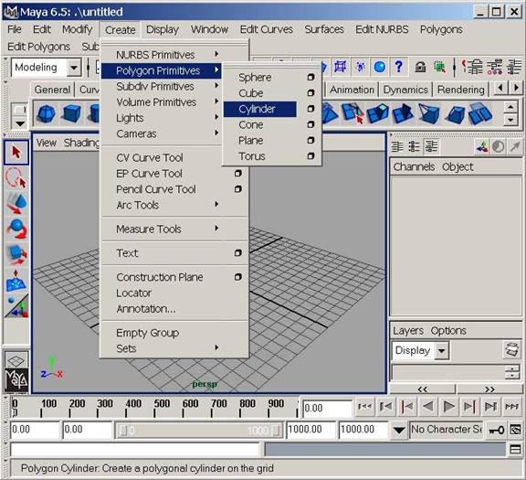
We shall start the modeling by creating a polygon cylinder primitive by accessing Create>Polygon Primitives>Cylinder.


Fig 10-1

Now we need to switch to the component mode in order to make changes to the primitive cylinder that we just made.

Press F8 to go to the component mode and select the point option.


Fig 10-2 Component Mode options

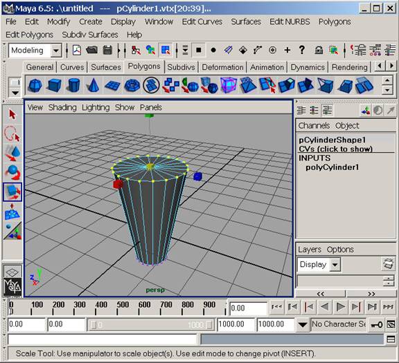
Select the top vertices as shown yellow in the given figure. Use the Scale transform tool and using the middle yellow cube, click and drag the mouse to increase the scale.


Fig 10-3 Editing the primitive in component mode

Let us call this object that we modeled, “limb unit”. We shall be using this object by making copies of it and resizing them and then fixing at the required locations. This unit will form the limbs of our Robot. You can use the Move Transform tool, and Rotate Transform tool to position the object in the scene.

If you are already in component mode, press F8 to come out of it. First of all start by creating a copy of the existing object by pressing keyboard shortcut Ctrl D. Use the Move transform tool to move the new created object to a side.

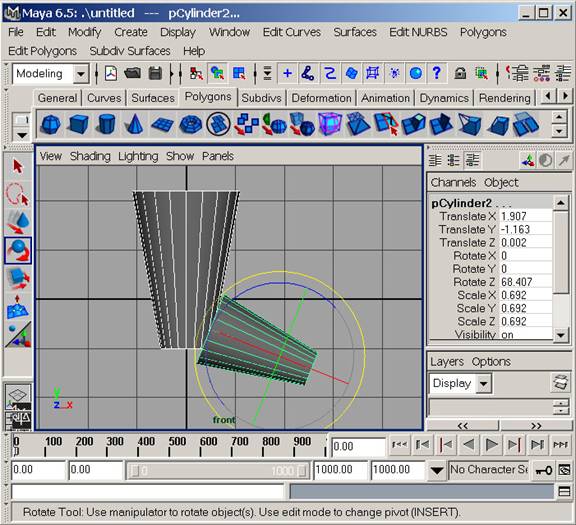
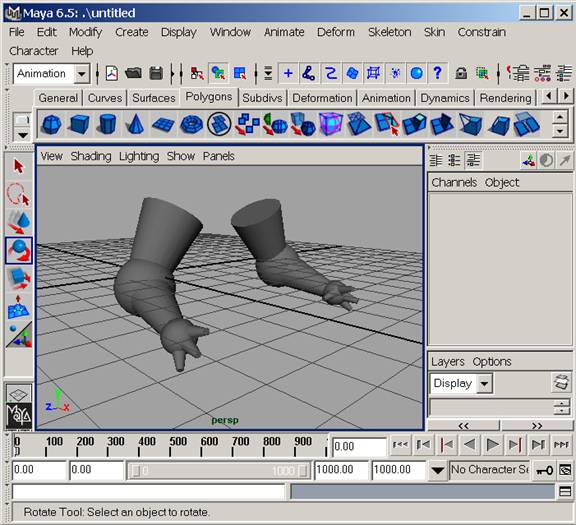
Use the Scale tool to downsize the newly created limb unit and then use the Move tool and rotate tool to get both of the objects in the shape, orientation and position as shown in the given figure.


Fig 10_4

Use the Copy, move, scale and rotate tools to make 4 more limb units out of the original one and resize, position and orient them to form the 3 fingers and 1 thumb of the Robot.

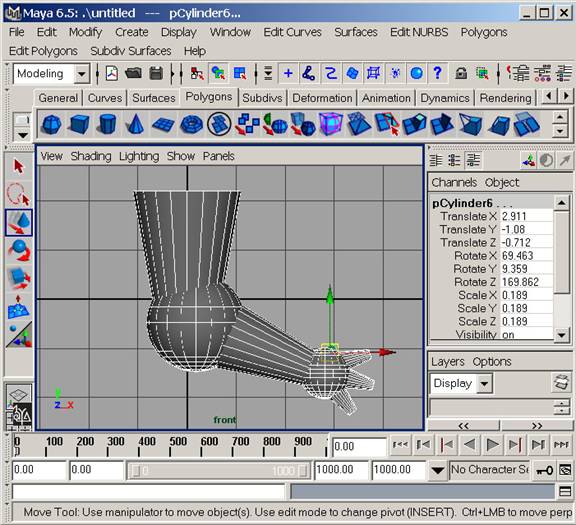
Using the similar techniques explained above, this time create a polygon sphere primitive and use its copies to form the joints of the limbs as shown in the given figure.


Fig 10-5

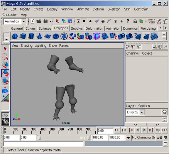
Next, we need to make another similar limb structure as shown in Fig10-5 in order to form the other arm. You can rotate both the arms to be a bit inclined outwards from the elbows. Match the orientation and position of the two arms with the one shown in the following figure.


Fig 10-6

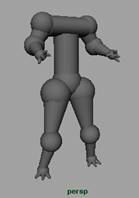
Now, that we have both the arms of the Robot ready, we are not far from developing the complete humanoid. We can continue developing the legs of the robot in exactly the similar manner that we have used till now. After completing the legs, the robot will somewhat look like in the figure 10-7. However, at this point of time you may want to use your own creativity and try different looks for the Robot.


Fig 10-7

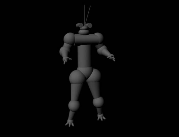
In the next step we shall use few more spheres and a cylinder to make the torso of the robot as shown in the next figure.


Fig 10-8

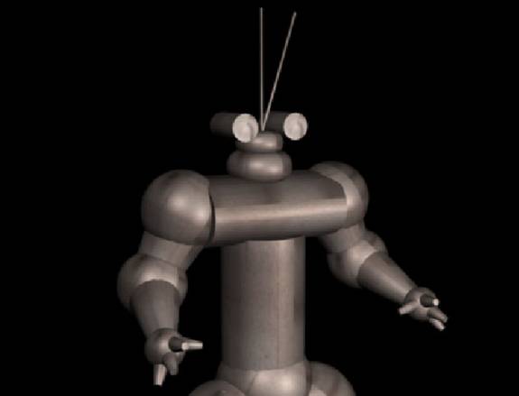
The process had been pretty simple so far. We have been using just two basic polygon primitives i.e., cylinder and a sphere. Now, lets make use of another primitive i.e., Torus. Create a Torus from the create Menu. Resize and position it to form the elements of the Neck. You can go a step ahead by using the cylinder primitives to form the camera like structure that are substitute for the eyes in our Robot. A real small radius cylinders can be used to form something that can act as an antenna receptor. The final modeled structure of the Robot is shown in this rendered image.


Fig 10-9 The complete model

Now, we shall texture this Robot. Lets start by opening the Hypershade , Windows>Rendering Editors>Hypershade. Select the Blinn material and name it to Robotexture.

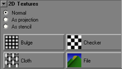
Create a Blinn Material - Create (on the Hypershade menu)...>Materials...>...Blinn, or use the side bar. Double-click the new material to open the attribute editor. Change the material name to Robo_Blinn or so. Click the box next to the color slider, a new option window opens. Choose Normal and click File to assign a bitmap as the material color.


Fig 10-11

You can select any metal texture image for the purpose. I have included one that we are going to use now with the accompanying source file for this tutorial.

Repeat the procedure to assign the same file to the specular color. Now, on the perspective view shading menu choose smooth shade all and turn on Hardware texturing.

Select the robot, shift select the Material in the Hypershade, right-click-it and "assign material to selection". Your robot is now textured.

Now, before we render out our robot, we need to setup a simple light rig for the purpose.

Create a point light Create>Lights>Point Light, open the attribute editor (control-a), expand the shadows options and turn depth map shadows on. Press 7 to view the lighting in the view port, duplicate the light 2 or 3 times and move them around the robot until you get the desired look.

Open the render globals window from Window>Rendering Editors>Render Globals. Select the anti aliasing quality to production. Ready to go, Render out the scene.


PLAY 13 Card RUMMY Online with friends,family & Win Cash Prize